Planar Laser-Induced Fluorescence (PLIF)
Planar laser-induced fluorescence is a species specific method in which the probe interacts only with particular energy levels of a chosen species in the flow. A narrowband laser beam is tuned to the absorption line of the species of interest and passed into the shock tunnel flow. The light is absorbed by the species present in the flow and re-emitted in all directions at wavelengths characteristic of the species. The technique can be used for two-dimensional imaging by forming the laser beam into a sheet and then passing it into the flow. By using a camera imaged at right angles to the sheet, a two-dimensional image is obtained which is related to the distribution of the species in the flow. Unlike interferometry, the image recorded is not integrated across the flow but results only from fluorescence in the thin sheet passed into the flow which can give high spatial and temporal resolution.

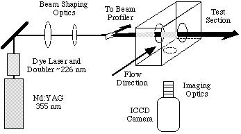
The experimental arrangement for performing PLIF measurements is shown below. Our measurements have been performed on nitric oxide which has strong absorption bands in the ultraviolet and provides good non-resonant fluorescence which can be easily filtered from scattered laser light. Nitric oxide is also suitable as it is often present in high temperature air flows or, if not, can be added to the test gas before a measurement is performed. The ultraviolet laser light used for NO excitation is obtained by frequency doubling the output of a tunable dye laser pumped by the third harmonic of a pulsed Nd:YAG laser. A small portion of this beam is separated and passed through a flame for tuning purposes. The remainder is formed into a sheet and passed through a fused-silica window into the test section parallel with the flow. Immediately prior to the window, a beamsplitter is placed to direct a small amount of the beam onto a dye cell. The resulting fluorescence from the test cell is imaged onto a CCD camera and is later used to correct the PLIF image for variations in intensity across the beam. The fluorescence from the flow is imaged onto an intensified CCD camera which can be gated down to durations of 5 ns. To discriminate against scattered laser light as well as to remove natural luminosity from the flow, a number of filters and/or wavelength dependent mirrors are used. Even so, a small background signal is observed which can be recorded and subtracted from the PLIF images.
The laser is tuned to the absorption line originating from a particular rotational energy level in the zeroth vibrational level of the NO ground state. The light excites the molecule into a particular rotational level of the zeroth vibrational level of the excited A electronic state. Collisions in the gas rapidly transfer this population to other rotational states (rotational energy transfer), to other vibrational states (vibrational energy transfer) and back down to the ground state (quenching). Molecules remaining in excited states can fluoresce decaying down to various vibrational levels in the ground electronic state. The fluorescence collected is the broadband fluorescence from the collisionally redistributed upper states to the lower electronic state. This signal is dependent on a number of parameters including collection optics efficiency, the number density of the absorbing species, the temperature of the gas, the spectral convolution of the laser and absorption lineshapes, the strengths of the transitions and the electronic quenching rate for the upper state.

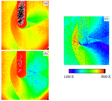
PLIF images are shown adjacent - (a) and (b). The measurements were performed in the small Drummond shock tunnel using a mixture of 5% NO in nitrogen as the test gas. The images show flow from left to right over a small cylinder. The laser sheet enters from the bottom of the picture resulting in the shadow seen above the cylinder. In each image there is a significant signal in the freestream ahead of the shock due to the NO present in the test gas. As the flow passes through the shock this signal can either increase or decrease dependent on the energy level probed and the amount of collisional quenching that occurs.
In principle it is possible to determine the absolute population of these rovibrational energy levels from the strength of the signal. In practice this is difficult as the detection system must be carefully calibrated and uncertainties remain on collisional quenching rates. However, to determine temperature, it is only necessary to measure the relative populations in two rotational levels. By taking the ratio of two images recorded using transitions from two different lower states, the detection efficiencies and quenching rates can be presumed to be the same in each case and cancel out. The temperature thus determined is given in (c) above. It shows clearly the increase in temperature of the gas as it passes through the shock front with the maximum temperature being observed immediately in front of the body where the gas is brought almost to rest. Due to the high pressure in this region, there is strong quenching of the signals and thus the temperature determination is less accurate. The figure also shows the decrease in the temperature of the gas as it passes around the body. Comparisons of these measurements with computer simulations of the flow are in progress.